ATTENTION:
With the AMM-P4 you are able to set up a motor control system with HIGH-VOLTAGE and virtually UNLIMITED OUTPUT POWER.
If you use this product, you do it on YOUR OWN RISK AND RESPONSIBILITY !
The AMM-P4 is not intended and not authorized to be used in applications in which the failure of the product could create a situation in which damage, personal injury or death may occur.
If you do not agree with the above statements, please do NOT BUY and do NOT USE this product.
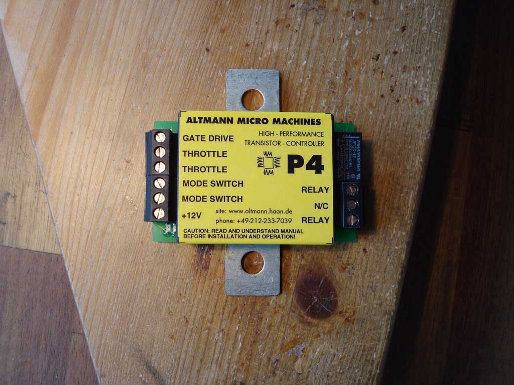
Take a look at the AMM-P4 principle of operation.
The AMM-P4's output-PWM drives the gate of a transistor, which in turn passes current through the electric motor.
The PWM frequency is 16 kHz.
The amount of electric drive to the load is user-controlled by the throttle and the mode switch, which are connected to the P4 module as follows.
Current that is flowing through the transistor is measured by the AMM-P4's integrated precision shunt resistor.
The current-limit is determined by the shunt-resistor value and the AMM-P4's trim-pot adjustment.
When selecting the power transistor(s), it should be taken into consideration that the AMM-P4 allows peak-currents of twice the current-limit value.
The AMM-P4 module can control any kind of MOSFET - as well as IGBT transistors.
MOSFET transistors can have (much) lower conduction losses at low currents and low voltages compared to IGBT transistors. This is their main advantage and the main reason they are used in small power applications.
However when the supply voltage approaches to 100V and above, MOSFET transistors are not very much suited anymore, as high-voltage MOSFETs cannot be made with ultra-low Rds-On, which means you need more and more transistors in parallel, in order to be able to pass enough current at low losses.
IGBT transistors are not so efficient for low currents, however they are more rugged and can be used in higher-voltage applications (up to 1000 Volt or more), while at the same time suppying high currents.
Given the fact, that switching losses are about the same in MOSFET and IGBT transistors, the advantage of the MOSFET lies only in smaller conduction losses at low currents.
Grossly simplified, IGBTs are for high-power to very high power applications, while MOSFETs are great for low to intermediate power.
The AMM-P4 can drive power transistors in parallel connection. The gate-drive output voltage of the P4 module is 17 Volt, and the gate-drive output current can be as high as 12 Amps (peak value). This makes the P4 module capable of driving the biggest power transistors.
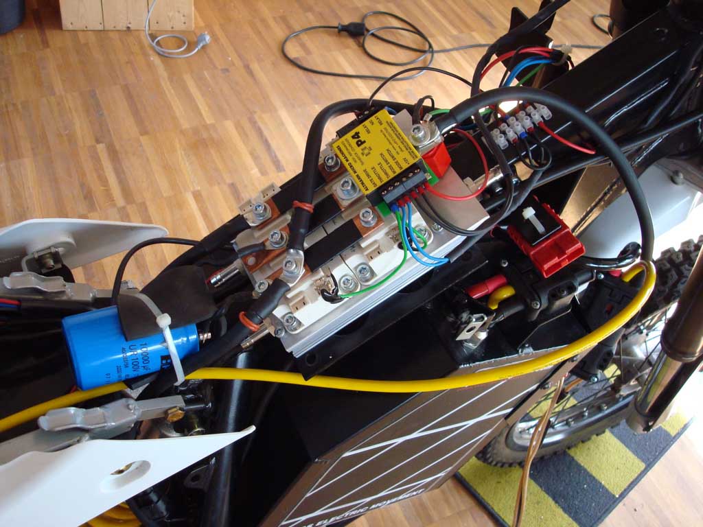
See below: AMM-P4 driving two Semikron IGBTs in parallel, each rated 1200V, 400 Amps.
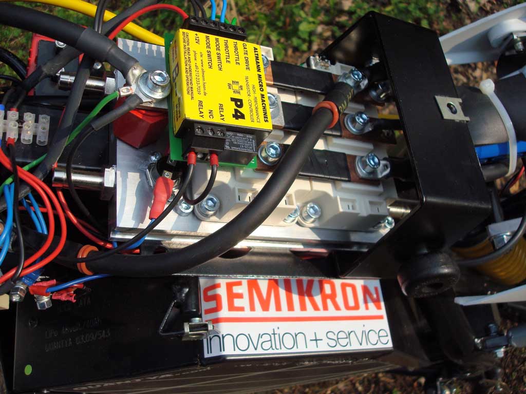
The IGBTs in the above pic are the Semikron SKM400GAL12E4, available from Sindopower, and they already come with a freewheel diode.
They are connected to the AMM-P4 as shown here, and a parallel connection would look like this, also parralelling the transistor connection details.
When it comes to weight power ratio, the above assembly is hard to beat: 2kg for about 100 kW conservatively estimated output power.
From a thermal standpoint it seems to be much more efficient to use big transistor modules instead of many small individual transistors in parallel. One reason is the sheer size of the contact area between transistor chip and heatsink, the other is that the big SKM transistor's cooling area is electrically isolated, while small transistors are not electrically isolated, which would require further heat-resistive, electrically isolating thermal coupling.
Applying a very thin coat of thermal grease to the SKM's heat-sink-area, you can easily do that yourself:
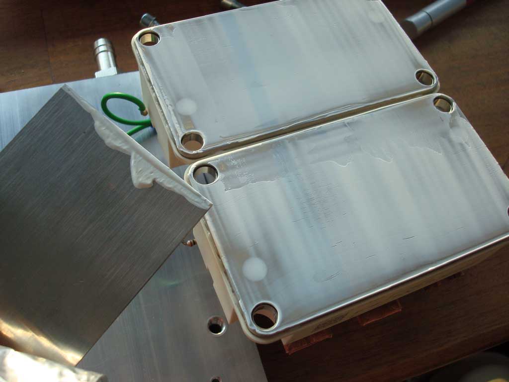
The big SKM transistors are mounted to a aluminum plate. As they are electrically isolated, the aluminium-plate is also isolated and may be bolted to more substantial structures for further cooling.
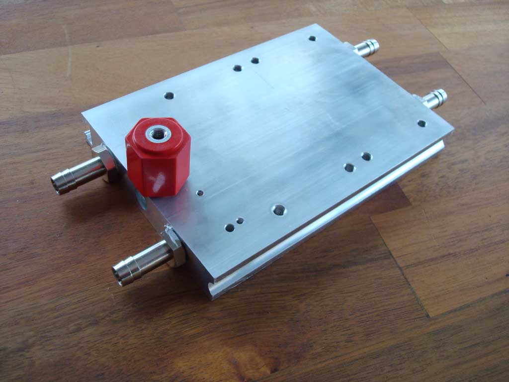
Even higher energy output from a transistor is obtained with the help of water cooling. Water is pumped through the cool-plate. A cool-plate is an aluminum plate with holes that can pass water (water has a very high heat-capacity). Water cooling should not be considered as something you have to do, it is rather something you CAN DO, when air cooling does not do the job anymore.
Shown below, aluminum cool-plate with isolator (red) in front. Here's an example of a possible cool-plate assembly.
The AMM-P4 module should be powered by plus 12V DC with respect to the battery minus. If main battery voltage is on higher voltage, 12V DC can either be provided with a DC/DC converter or an auxiliary 12V battery. An absolute maximum value of 18V DC is tolerated by the AMM-P4 module without destruction.
A regulated charge-pump inside the AMM-P4 module generates a gate drive of 17 Volt.
The AMM-P4 features two different modes of transistor control, which can be selected with a switch that is connected to the mode-switch-inputs. If switch is open (or mode-switch inputs are left unconnected) then the throttle input directly controls PWM duty cycle (voltage).
If switch is closed, then the throttle input controls current. To be more precise, in this mode the AMM-P4 adjusts PWM duty-cycle so that the desired current-value is flowing. This happens in a high-speed (real-time) regulation loop.
When driving a DC electric motor in the voltage control mode, the motor behaves as if controlled by a very aggressive speed- (cruise) control, one which only knows two states: full power or zero power. In other words: the motor speed is controlled, regardless of current (torque).
When the same DC motor is driven in current mode (Altmann Tru-Torque), the throttle input controls the torque of the motor regardless of speed. This drive mode is similar to that of an Otto-engine, where the throttle also controls torque, however the AMM-P4 's throttle - torque relation is much more accurate compared to a combustion engine.
This is a funny phenomenon:
With an electric DC motor, the relation is exactly reversed: you need to control speed in order to regulate constant torque.
The AMM-P4 lets you switch drive modes any time, but they only take effect after throttle-input cycles through zero-position.
Please click the following link if you want to learn more about the Altmann Tru-Torque drive mode.
One of the AMM-P4's interesting features is that it permanently monitors transistor operation, and in the event it detects a transistor failure, will switch the on-board relay off. The user should use the AMM-P4's on-board relay in order to power the main contactor, so that in case of a transistor failure, battery power is completely disconnected from the system.
A transistor failure can result in a transistor short-circuit which means uncontrollable full-throttle for the connected DC-motor, a highly dangerous situation. Please note that transistor failure detection and contactor shut-down can only work, if current-measurement (shunt) and on-board relay are connected correctly.
There are other reasons for shutting down the main contactor (motor-temp, heatsink-temp, BMS, etc) therefore a contactor security chain should be set up as shown in this diagram.
Click the next link for a diagram of the cicuit shown below.
The AMM-P4's current measurement is crucial to perform all of the following tasks:
If the internal current measurement does not work for any reason (i.e. shunt not connected or hardware defect) a dangerous situation can occur.
The AMM-P4's software has implemented the following security mechanisms to ensure a working current measurement or to prevent damage in case of wrong current-measurement:
On Power-On the AMM-P4 does the following security checks before it activates the on-board relay:
A red LED communicates a variety of error-codes.
Since the AMM-P4 drives MOSFET or IGBT Transistors, which have an isolated gate, it is theoretically possible for a user to set up a fully working power system where the transistors are supplied by a very high (lethal) voltage (i.e. today's IGBT transistors are rated to withstand 1200Volt).
However, when a transistor fails it often happens that its gate loses isolation, so in-turn the AMM-P4 gate drive output will be on high-potential too, which can cause immediate destrution of the AMM-P4 unit, resulting in uncontrolled behaviour. Also high-voltage may further propagate to the throttle- and switch-inputs of the AMM-P4 right to the user-operated throttle- and mode-switch, possibly causing injury or death.
Should the user set up a high-voltage system a fully isolated external gate driver must be used. Also the relay outputs have to be decoupled from high voltage using a second relay of appropriate rating.
The AMM-P4 module is rated 12V supply and its absolute maximum rating is 18 Volt, higher voltages will lead to immediate destruction of the AMM-P4 module.
The cycle analyst is an interesting product developed by Justin Lemire Elmore of ebikes.ca, which can be connected to the AMM-P4 in order to display supply voltage, amps, kilowatts, amphours and a lot more things ...
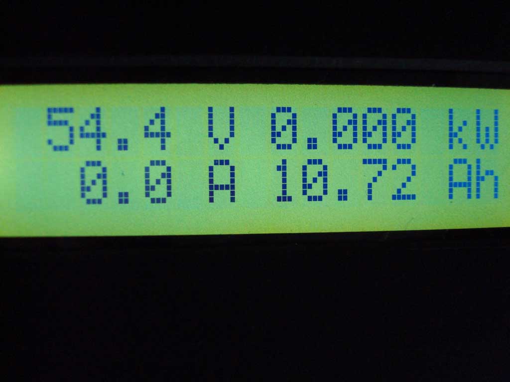
The following link shows the connection of the cycle analyst to the AMM-P4.
The AMM-P4 is available with three different shunt resistors:
The shunt is soldered to the AMM-P4 module and is not user-replaceable. However it is always possible to increase the current rating by adding a 2nd (or more) shunt resistor in parallel (mounted as a sandwich to the fixed shunt).
The AMM-P4 price is EUR 1049,- incl. shipping and 5 years limited warranty.
Please note that the AMM-P4 comes as single-module and you need to source transistors, capacitor, etc. yourself.
Orders are taken by email, questions too :-)
ALTMANN MICRO MACHINES ... Dipl.-Ing. Charles Altmann ... Erlenstr. 15 ...42697 Solingen ...Germany
phone +49-212-233-7039 ... email